Triple axis acceleroemter with PICAXE

LIS302DL by ST
Acceleroemters were once very expensive peicies of eqipment, not the case anymore. There are now dozens of small, cheap, simple acceleroemter chips out there for the general publlic. This turnaround was no doubt facillitated by the prevelenace of acceleroemters in so many of todays’ consumer electroincs. For example in the iphone an acceleromter is used to sense it’s orentation so that it can rotate the screen (actually a very simple implemtnation), and in the Nintendo Wii. So with all these demands, manufacutres a driven to produce better, cheaper and smaller IC’s, and the benefits filter down to us.
I want to share what I have learned on how to use the LIS302DL 3-axis accelerometer breakout board. It’s a pretty cool sensor with I2C or SPI interfacing. You can buy it from SparkFun who make the breakout board or from cool components who stock it in the UK. You could have one of these sensors in your hands and working for under £25. For anyone who wants to add “tilt sensing” to your projects the LIS302DL is a good choice.
I make it sound easy to use, and it is, but for me it was not the case. I must have spent two days reading the datasheet over and over trying to extract useful information, and trawling the web trying to find any information on how to use it. I did not find any PICAXE related information on the unit but I found some AVR and PIC code written in C which I read and reworked into PICAXE code. So hopefully someone will find this information useful and save them some time getting up and running with this little unit.
Here is a list of all the documentation that I found useful:
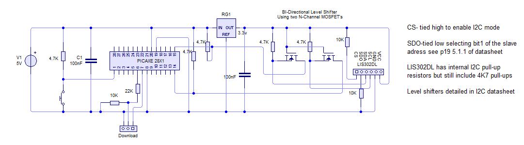
- To set up the circuit you need a level shifter because the accelerometer runs on 3.3V and PICAXE on 5V (if you can run the PICAXE at a lower voltage then I would guess you would be ok). Details on the level shifter are on p43 18.1 on the I2C datasheet.
- Once the circuit is set up you can begin to communicate with the module, I am using I2C. Its default is 100 KHz i.e. i2cslow.
- Find the slave address according to p19 5.1.1 of the datasheet
- Your first communication should be to initialise the module. Write to CTRL_REG1 (20h) to disable power down mode and enable the axis for use. Register details are from p24 of the datasheet.
- There is a register called WHO_AM_I (0Fh), which has constant value and can be read at any point and used as a sort of sanity check.
- So now to begin taking data from the module, we will be monitoring the STATUS_REG (27h) and the ZYXDA Bit, when this Bit=1 new data is ready.
- We can then access the OUT_X/Y/Z registers and read their values. The thing to note here is that the data is stored as two’s complement because acceleration can be negative. PICAXE does not support two’s complement or negative numbers, so you need to make up some kind of procedure to deal with it. Hopefully my method is clear from the code, but all I did is use the fact that if the number is more than 127 then it’s negative and subtracting it from 256 will give me the UNSIGNED number. I then used a variable to signal if it was a negative or positive output. I’m sure that there is a better method than mine out there to cope with two’s complement using PICAXE.
- So once you have the numbers you need to multiply it by the sensitivity of the device which is 18mg default (g as in gravitational force). The sensitivity is what each unit equals, so reading positive 10 from the X output means 10*18 = 180mg acceleration. See the application notes p32.
- So that’s reading the data sorted, but the output is not very steady so I average it over 10 cycles.
- You now have X, Y and Z data at your disposal!
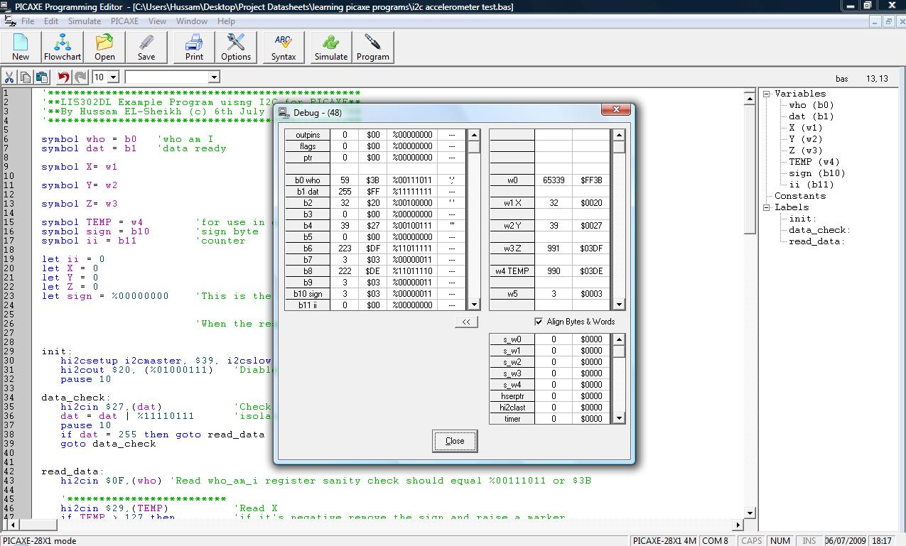
Here is my example code that simply outputs the data to a debug screen. (It’s in text file format, so just paste it into Programming Editor)
I have also attached my schematic and a print screen of the debug output. As you can see the debug screen shows a reading of 991mg or aprox 1g on the Z axis, which is what you wold expect as its axis is pointed towards the centre of the Earth. The sign byte is showing that the X and Y axis are both reading negative acceleration and of course Z is positive. With the averaging the noise on the readings is around +/- 10mg which is not bad.
You can also find the same entry on the PICAXE forum here.